
How To PLC Wiring In Control Panel The Automization
1. Relay. A relay symbol in a PLC wiring diagram represents an electromagnetic switch that can control the flow of electricity to different parts of the system. Relays are commonly used to connect and disconnect power to various devices such as motors, lights, and sensors. 2.
How To PLC Wiring In Control Panel The Automization
The following considerations will facilitate an orderly installation of a PLC: PLC I/O module installation Wiring considerations Recommended wiring procedures Wire size Wire and terminal labeling Wire bundling Special I/O connection precautions Connecting leaky inputs Suppression of inductive loads Fusing outputs Shielding I/O module installation
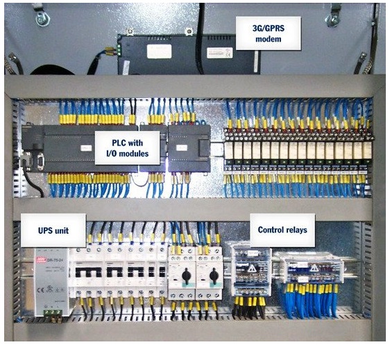
What is a PLC Panel? Panel Components Automation Ready Panels
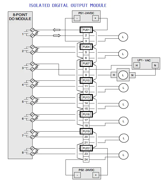
Wiring Diagrams of PLC and DCS The below list shows the basic types of wiring connections available for DI, DO, AI, and AO Signals: Digital Input (DI) Signals Single-wire Connection Two-wire connection Two-wire connection with Line Monitoring DI with Relay - Wet Contact DI with Relay - Dry Contact
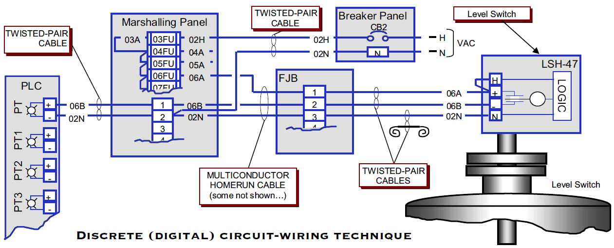
PLC Wiring Diagrams PLC Digital Signals Wiring Techniques
Join us here, get awesome perks, and support us, all at once:https://www.youtube.com/c/upmation/joinRead the full blog post at https://upmation.com/plc-w.

Basic Plc Circuit Diagram Pdf Wiring Digital and Schematic
Basic Electrical Design of a PLC Panel (Wiring Diagrams) - Free download as PDF File (.pdf) or read online for free. When design PLC, we need a Panel to place our PLC safe and easy to manage. Following a guide to design PLC Panel is good to practice the good Panel arrangement.

Basic electrical design of a PLC panel (Wiring diagrams) EEP
Wiring Diagram Of Plc Panel Programmable logic controllers (PLCs) are a critical component of many industrial control systems. The wiring diagrams that are used to connect and configure PLCs can be complex, but they are essential for ensuring that the system functions properly.
Panel eléctrico con PLC, Diseño básico (diagrama de cableado)
To be able to read an electrical wiring diagram of a PLC panel, you should have an understanding of these components. Let's take a look at these two types of electrical components: A) PLC Panel Power Components Rotary Disconnect: It is used for connecting incoming power lines/wires. It can include fuses or not.
Wiring Diagram Of Plc Panel Wiring Diagram Line
1. Check the heating values of devices and the panel (kW). Check the heating value of each device located in the control panel and then find the total heating value. Generally speaking, the heating value indicates the power consumption, so you can assume that the power consumption equals the heating value.
Ban genius sunset plc layout
Each page of this wiring diagram shows the exact wiring for different sections of this control panel. In the back of the Emergency Stop push button, you see that we have four wires, just as.
PLC Wiring Diagrams PLC Digital Signals Wiring Techniques
Now we have to understand that -v (0V) We need to create a potential difference of +V (24V) across these input terminals. Then only this PLC will recognize that there is some input. For example, if i connect this V over here (IN ). And then i am going to simulate that. You will see this is ON.

Wiring Diagram With Plc Wiring Digital and Schematic
Please Subscribe to Easy PLC Training Sessions for more Videos and TrainingLink for Part # 1 PLC Tutorial for beginners Part #1 Hardware preview https://www..

Allen Bradley Plc Wiring Diagram Wiring Diagram Networks
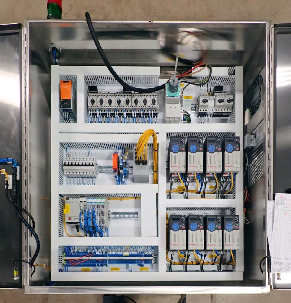
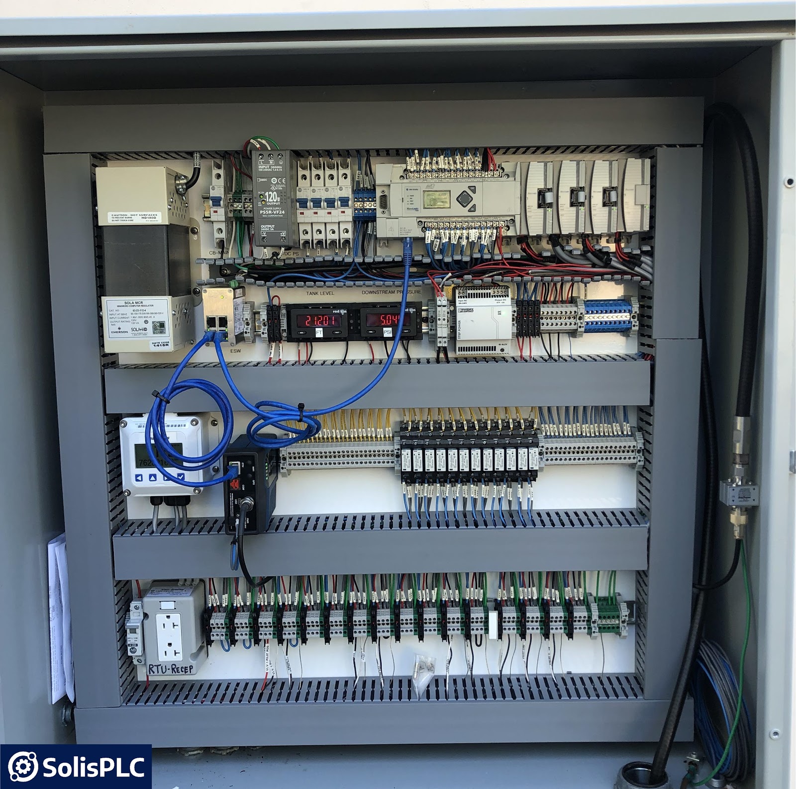
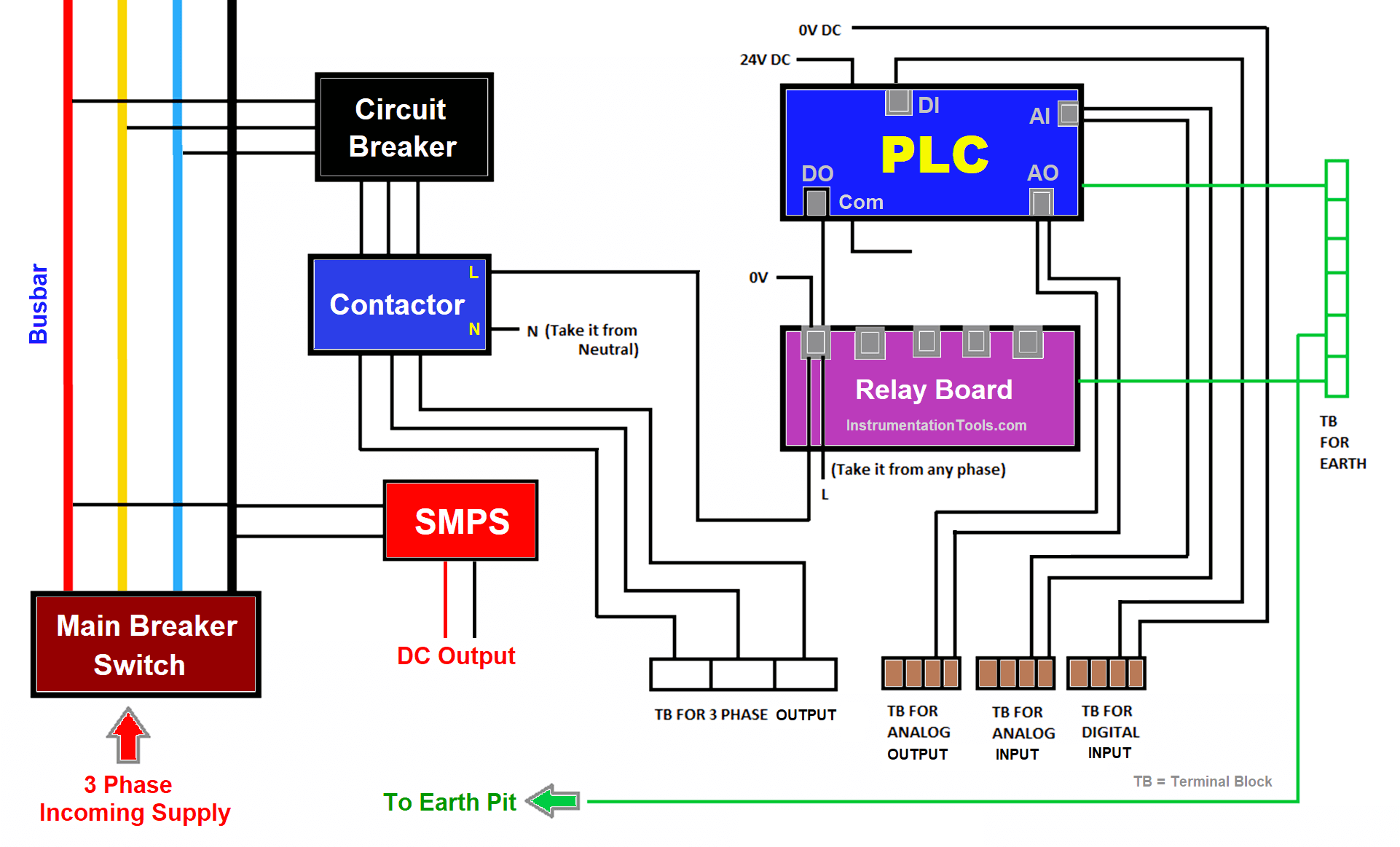
The PLC panel consists of the main breaker switch, bus bar, circuit breakers, relays, contactors, PLC, fuses, SMPS, terminal boards, utility sockets, and earthing points. Main Breaker Switch Let us start with the main breaker switch. This is the point where the main power supply (3 phases) is connected (R, Y, B, N).
The Basics of Reading PLC Panels and Wiring Diagrams Do Supply Tech
Plc Panel Wiring Diagram Symbols: Understanding the Language of Automation As automation continues to revolutionize commercial and industrial operations, the ability to read and understand Plc Panel Wiring Diagrams is an ever more critical skill. These diagrams are used to represent the wiring of a control system and make it easier for technicians to diagnose, troubleshoot, and work with new.

Plc Control Panel Wiring Diagram on plc panel wiring diagram
In this comprehensive video guide, we dive deep into the art of wiring a Programmable Logic Controller (PLC) control panel. Whether you're a seasoned enginee.

PLC Panel Electrical panel wiring, Electrical projects, Electricity
Products Discounted Below Trade Price. Buy online from TLC Electrical today! Don't Buy From Anyone Else Until You've Seen TLC Electrical's Prices
Single Line Wiring Diagram Plc Manual EBooks Plc Wiring Diagram
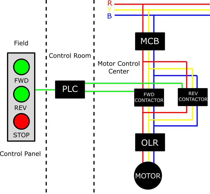
Electrical wiring diagrams of a PLC panel In an industrial setting a PLC is not simply "plugged into a wall socket". The electrical design for each machine must include at least the following components. Transformers - to step down AC supply voltages to lower levels